Opamp
Contents
Integrator
Inverting

The output signal is a scaled and inverted integral of the input signal: 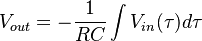
There is a problem with this circuit though—the integrator is only good if the Vout is less than the maximum output voltage of the op-amp. Our integrator is thus not very useful for low frequency signals, because the charge will store up on the capacitor and eventually saturate the op-amp. Even if we have a high frequency signal, any DC offset will add up in the capacitor over time. We can remedy this problem by adding a shunt resistor Rs across the capacitor to bleed off any long-term charges that store up in the capacitor. As a rule of thumb, Rs should be greater than 10R1.
Input bias current flowing through R1 and Rs can generate a small DC offset, and we can try to cancel it out by adding another resistor R2 between the non-inverting input and the ground such that: Failed to parse (Missing <code>texvc</code> executable. Please see math/README to configure.): R_2 = \frac{R_1 R_s}{R_1 + R_s}
Non-inverting
Buffer (Voltage follower)
Use this circuit when you have a signal of high impedance ( can supply only a little current ) that you want to connect to another circuit that draws a significant current ( up to about 10 ma for the typical op amp. ). For example if you wish to measure the output of a voltage divider with a 0 to 1 ma meter a unity gain buffer might be just what you need. This circuit is also know as a voltage follower.
The unity gain buffer has an output voltage just the same as the input voltage. The advantage is that the input circuit does not “feel” the output. That is the input acts pretty much like a very large resistor ( many mega ohms or more ) connected to ground, and the output supplies whatever current ( up to about 10 ma ) is necessary to maintain the output voltage. Here is the circuit:
Where
- INPUT the input signal you wish to buffer
- RIN the input resistor, often 0 ohms.
- OPAMPA Any general purpose op amp, often connected to + and - power supplies
- RFB the feed back resistor
- OUTPUT the output
Discussion: The values of RIN and RFB are not very critical and are normally 0 ohms, just a straight connection. The op amp here is a quad or 4 op amp part, we are using just one section of it. Power needs to be supplied to pin 8 and 4 in the usual way for op amps. This circuit uses very large feedback (unity) and for this reason has poor stability margins. This may cause the output to go into oscillations when connected to certain loads (typically capacitive). Check the datasheet of individual opamps for details and remedies.
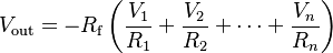
Summing amplifier
Inverting
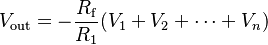
A summing amplifier sums several (weighted) voltages:
- When Failed to parse (Missing <code>texvc</code> executable. Please see math/README to configure.): R_1 = R_2 = \cdots = R_n
, and  independent
- When


- Output is inverted
- Input impedance of the nth input is
 (
( is a virtual ground)
Negative impedance converter

A NIC, shown to your left, is a negative impedance converter. Looking into Vin, the NIC appears to have an impedance −Z to ground. In other words, the circuit inverts it internal impedance Z to −Z.
Gyrator

A gyrator is a circuit that converts an impedance of Z to R2/Z. Gyrators can be synthesized from two NICs as show in the block diagram below. The components to right of each indi-vidual NIC form the impedance Z of that particular NIC.