RF-Microwave basics
Contents
Scattering parameters (S-parameters)
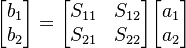
S-parameters are defined in terms of incident and reflected waves at ports. S-parameters are used primarily at UHF and microwave frequencies where it becomes difficult to measure voltages and currents directly. On the other hand, incident and reflected power are easy to measure using directional couplers. The definition is
where the  are the incident waves and the
  are the reflected waves at port k. It is conventional to define the and in terms of the square root of power. Consequently, there is a relationship with the wave voltages.
For reciprocal networks  . For symmetrical networks
  . For antimetrical networks
  .
For lossless reciprocal networks
.
For lossless reciprocal networks  and
and 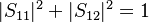 .
.
Complex linear gain
The complex linear gain G is given by
 .
.
That is simply the voltage gain as a linear ratio of the output voltage divided by the input voltage, all values expressed as complex quantities.
Scalar linear gain
The scalar linear gain (or linear gain magnitude) is given by
 .
.
That is simply the scalar voltage gain as a linear ratio of the output voltage and the input voltage. As this is a scalar quantity, the phase is not relevant in this case.
Scalar logarithmic gain
The scalar logarithmic (decibel or dB) expression for gain (g) is
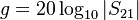 dB.
dB.
This is more commonly used than scalar linear gain and a positive quantity is normally understood as simply a 'gain'... A negative quantity can be expressed as a 'negative gain' or more usually as a 'loss' equivalent to its magnitude in dB. For example, a 10 m length of cable may have a gain of - 1 dB at 100 MHz or a loss of 1 dB at 100 MHz.
Insertion loss
In case the two measurement ports use the same reference impedance, the insertion loss IL is the magnitude of the transmission coefficient Template:Math expressed in decibels. It is thus given by:
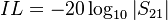 dB.
dB.
It is the extra loss produced by the introduction of the device under test (DUT) between the 2 reference planes of the measurement. Notice that the extra loss can be introduced by intrinsic loss in the DUT and/or mismatch. In case of extra loss the insertion loss is defined to be positive. The negative of insertion loss expressed in decibels is defined as insertion gain.
Input return loss
Input return loss can be thought of as a measure of how close the actual input impedance of the network is to the nominal system impedance value. Input return loss expressed in decibels is given by
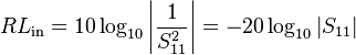 dB.
dB.