Entanglement lab
Contents
Intro
We have to assemble the undegraduate experiment. The basic idea is published here. [1]
Related articles:
- "Comparing measurements of g2(0) performed with different coincidence detection techniques"
The more information can be found in Berkley undergraduate lab [2], the student manual is available [3] Some information can be found on [4].
Theory
Some practical formulas
Beam separation as a function of optical axis angle Theta and block length D: 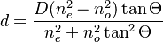
Type I for entanglement
As opposed to type II phase matching that produces orthogonally polarized photons in parametric down conversion (PDC), the type I PDC process produces identically polarized photons in the output signal and idler modes (labels s and i below).
Normally the output state from type I PDC is not entangled: to get the required phase matching in the nonlinear material, the pump polarization must be fixed. Both the PDC photons may then either be horizontally or vertically polarized. An often-used trick is to employ two similar nonlinear crystals (placed one after the other with their optic axes orthogonal) and sending a pump with a 45 degree polarization . If the crystals are thin enough to simultaneously lie inside the coherence length of the pump, and losses between the first and second crystal are negligible, then a pump photon is equally likely to excite the PDC process in either of the two crystals. In that case, the output state may be approximated as |Hs,Hi⟩+eiϕ|Vs,Vi⟩ which is an entangled state. The relative phase ϕ is a function of the phase matching, thickness of the crystals, etc.
Components
Electronics
| Part name | Part number | Digikey | Ebay | Ebay price |
|---|---|---|---|---|
| FPGA | Cyclone FPGA | P0082-ND, 115.06 CAD | ||
| Arduino | DUE | 1050-1049-ND, 49.89 CAD | ||
| Keypad | 1528-1136-ND, 5.27 CAD | |||
| Display | 1528-1536-ND, 26.61 CAD | |||
| AC-DC converter | 945-2212-ND | |||
| USB connector | A111306CT-ND | |||
| Arduino | ||||
| Arduino |
Optomechanics
Missing: Beam displacer adaptor
Fibers
| Part Number | Fiber Type | Connector Type | Diameter | Numerical Aperture | ||
| Core | Cladding | Outter | ||||
| SPCM-Q9 | Multimode | FC/FC | 100 um | 140 um | 2.5 mm | 0.29 |
Missing: 2x2 Fiber coupler FC/FC, 850nm 62.5 um/125
Multimode Fused Fiber Spliter Oz-optics multimode Fiber fused coupler ( datasheet)
Fiber mechanics
- Fiber coupling stage option 1:
- f = 11.0 mm, NA = 0.25, Mounted Geltech Aspheric Lens, AR: 600-1050 nm C220TMD-B $71.00
- Fiber coupling stage option 2:
- Fiber Collimation Pkg., 780 nm, f = 11.07 mm, NA = 0.26 FC/PC F220FC-780 $148.00
- FC/PC to FC/PC Dual L-Bracket Mating Sleeve ADAFCB2 $54.50
SPCM
Lasers
Diode lasers are bought here.
Crystals

| Crystal | Information |
| PABBO5050-405(I)-HA3 | Paired BBO crystals, size 5x5x0.5mm(each), cut for Type I SPDC pumped by 405nm with the half opening angle of 3 degrees. The two crystals mounted in a 1" holder with one crystal rotated by 90 degrees about the axis normal to the incidence face |
| NCBBO5050-405(I)-HA3 | BBO crystal, Size 5x5x0.5mm, cut for Type I phase matched SPDC pumped by 405nm with the half opening angle of 3 degrees, AR coated, OD 1" mounted |
| NCBBO5300-405(I)-HA3 | BBO crystal, Size 5x5x3.0mm, cut for Type I phase matched SPDC pumped by 405nm with the half opening angle of 3 degrees, AR coated, OD 1" mounted |
|
Wavefront distortion: |
less than λ/8 @ 633 nm |
|
Clear aperture: |
> 90% central area |
|
Flatness: |
λ/8 @ 633 nm |
|
Scratch/Dig: |
10/5 to MIL-O-13830A |
|
Parallelism: |
better than 20 arc seconds |
|
Angle tolerance: |
Δθ < +/-0.25o, Δφ < +/-0.25o |
Coating: AR@405/810 nm for 405 nm pumped SPDC crystals
P-coating for pumps other than 405 nm unless coating is specified.
Experimental set-up
List of experiments
Single-photon interference
Quantum eraser
Hong-Ou-Mandel
Description of the HOM theory or here. If two photons are indistinguishable, we get regular N00N state with N=2. If we consider spectral bandwidth of a photon, we can take it in the form:
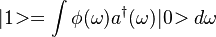 , where
  is spectral amplitude function. Before the BS we have next two-photon wavefunction with a delay in one arm:
 Following a regular BS transformation and applying measurement operator
 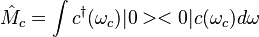 . The probability to get photon in each arm to coincide is given by:

Visibility of HOM dip
Visibilty is related to density matrices of the photons and is equal to purity of photons: 
Latest articles
The Hong-Ou-Mandel effect gives opportunity to measure attosecond delays and nanometer distances. "Lyons, Ashley, et al. "Attosecond-resolution Hong-Ou-Mandel interferometry." Science advances 4.5 (2018): eaap9416. "
[5],

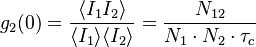
g2 function measurement
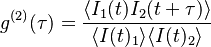
Degree of second-order coherence
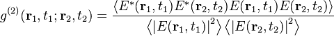
If the electric fields are considered classical, we can reorder them to express  in terms of intensities. A plane parallel wave in a stationary state will have
The above expression is even, 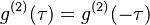 .
.
polarization entanglement
violation of the Bell inequality
Bell inequality was violated, although each time new assumptions are made, which open loopholes in proof of an initial statement. At this moment a few experiments were performed to close locality and detection loopholes simultaneously. These experiments were made with photon pairs, NV vacancies (the first to close both loophholes) and with neutral atoms. (So called Event-ready Bell test)
- "Significant-Loophole-Free Test of Bell’s theorem with Entangled Photons", PRL 115, 250401 (2015)
- "Strong Loophole-Free Test of Local Realism", PRL 115, 250402 (2015)
- PRL 119, 010402 (2017)
Experimental scheme
Assembly progress
May
- 17.05.17: Pat finished the rack above the optical table, optical table is on its legs
- 18.05.17: Sorted optical elements, Duncan finished his counting module
- 19.05.17: Duncan draws the plan. Crystals generate pairs on a specific angles determined by phase-matching conditions. All of the crystals have 3 degree an half opening angle.
- 23.05.17: Leveled a blue laser, collimated a red laser, mounted optics
- 24.05.17: sent beams of an alignment laser into fibers
- 25.05.17: installed crystal (long single crystal), saw counts on both SPCMs: 6 MHz of single counts, 1 MHz of coincidences
- 26.05.17: we have doubts regarding the coincidences. Possible check: misalignment of one of the fibers should lead to decrease of coincidences, although leave single counts similar.
- 30.05.17: we have more confidence that we see coincidences, which come from the same part of the cone. We decided to check entanglement between photons.
- 31.05.17: Duncan installed paired crystal, so we can observe polarization entanglement. We are basing our experiments on this article and this test.
June
- 1.06.17: Violated the Bell-inequality
- 2.06.17: Trying to find a way to interface available multi-mode fibers with a single-mode fiber beam splitter (TW805R5A2). Multi-mode fiber has a core 100um, fiber in the beam splitter 4.4um (uses this single-mode fiber); coupling efficiency with a use of ADAFCB2 is around 1% (multi-mode -> single-mode).
- 5.06.17: Found that only a small portion of photons emitted have Gaussian mode, so working with just single mode fibers is impossible. Single counts were 6*10^6 (multi-mode fiber) and 50*10^3 (single-mode fiber). Coincidence counts were negligible.
- 6.06.17: Alex thinks that multimode fiber coupler wouldn't work. We have seen some lab reports< where people used single-mode beam splitter. Don't have holders for beam displacers, planning to assemble regular interferometer () with mirrors and PBSs.
- 07.06.17: Alex doesn't want to try regular Mach-Zendner interferometer, asks us to change to interferometer based on beam displacers. Duncan build an interferometer, checked interference with a camera. No single photon interference.
- 12.06.17: We found that coherence length of the emitted photons scales as
 , where
  is the bandwidth of the filter in front of the multimode fiber. Usually people use 10 nm bandpass filter, we have only low-pass.
 - 16.06.17: Got results on
 for single photon and coherent cases
Milestones
Polarization entanglement
HWP for module #1: 0 degr
Pump HWP: 16 degr
Polarizer: 18 degr
| Singles, in thousands, Module #1 | Singles, in thousands, Module #2 | Coincidences | HWP, Module #2 |
|---|---|---|---|
| 156 | 175 | 11100 | 0 |
| 162 | 198 | 6300 | 22.5 |
| 160 | 212 | 1400 | 45 |
| 159 | 195 | 6200 | 67.5 |
| 159 | 178 | 11240 | 90 |
| 155 | 196.5 | 6200 | 112.5 |
| 164 | 215 | 1200 | 135 |
Bell-inequality violation
A typical CH74 (single-channel) experiment
Prior to 1982 all actual Bell tests used "single-channel" polarisers and variations on an inequality designed for this setup. The latter is described in Clauser, Horne, Shimony and Holt's much-cited 1969 article as being the one suitable for practical use.[7] As with the CHSH test, there are four subexperiments in which each polariser takes one of two possible settings, but in addition there are other subexperiments in which one or other polariser or both are absent. Counts are taken as before and used to estimate the test statistic.
(3) S = (N(a, b) − N(a, b′) + N(a′, b) + N(a′, b′) − N(a′, ∞) − N(∞, b)) / N(∞, ∞),
where the symbol ∞ indicates absence of a polariser.
If S exceeds 0 then the experiment is declared to have infringed Bell's inequality and hence to have "refuted local realism". In order to derive (3), CHSH in their 1969 paper had to make an extra assumption, the so-called "fair sampling" assumption. This means that the probability of detection of a given photon, once it has passed the polarizer, is independent of the polarizer setting (including the 'absence' setting). If this assumption were violated, then in principle a local hidden variable (LHV) model could violate the CHSH inequality.
In a later 1974 article, Clauser and Horne replaced this assumption by a much weaker, "no enhancement" assumption, deriving a modified inequality, see the page on Clauser and Horne's 1974 Bell test.[8]
31st of May
| HWP, module #1 | HWP, module #1 | Coincidences | Singles, module #1 | Singles, module #2 |
|---|---|---|---|---|
| 0 | 0 | 12300 | 162 | 190 |
| 0 | 45 | 1205 | 164.3 | 180 |
| 45 | 0 | 988 | 157 | 190 |
| 45 | 45 | 11300 | 152 | 179 |
| 45 | none | 12145 | 151 | 369 |
| none | 0 | 11500 | 318 | 171 |
| none | none | 25000 | 305 | 363 |
1st of June
| N(a, b) | N(a, b') | N(a', b) | N(a', b') | N(a', ∞) | N(∞, b) | N(∞, ∞) | S |
|---|---|---|---|---|---|---|---|
| 4271.3435114504 | 172 | 177.58 | 5177.4849785408 | 5362.9060402685 | 4581.5054945055 | 10000.768115942 | 0.48725 |
g2 function measurement

Single photons
| N3, module #3, single counts | N1, module #1, single counts | N2, module #2, single counts | N13, mod. #1 & #3, coincidences | N23, mod. #2 & #3, coincidences | N123, mod. #1, #2 & #3, coincidences | Sampling time, s | Averaged over N | g2(0) |
|---|---|---|---|---|---|---|---|---|
| 55261.6 | 14323.26 | 14344.026 | 1300.43 | 1403.29 | 2.1 | 1 | 121 | 0.064 |

Coherent state
Strongly attenuated red diode laser is sent through one of the paths, it comes to modules #1 and #2.
| N1, module #1, single counts | N2, module #2, single counts | N12, mod. #1 & #2, coincidences | Sampling time, s | Averaged over N | g2(0) |
|---|---|---|---|---|---|
| 49132.96 | 48341.5 | 23.6 | 1 | 100 | 0.99 |
 Which is normalized on the detection frequency (10 ns) rather than on the number of incident photons.
Possible extensions
- Quantum entanglement witnesses (Berkman), 4 detectors, FPGA Duncan
- Bell test with 4 SPDC
- Hong-Ou-Mandel (Mexican)-phys 598
Other educational experiments
- atomic clock (microwave source, amplifier, cavity 3.4 GHz)
- Ramsey spectroscopy
- radio-freq absorption
- optical pumping manual
- mode-locked laser
- harmonics generation
- titan-saphire
Questions:
- do we have extra fiber coupling stage?
- FPGA Duncan,adding 4th channel
List of cites
- ↑ Colgate description of the experiments
- ↑ Design manual
- ↑ Student manual
- ↑ Hank Oregon
- ↑ The Hong–Ou–Mandel interferometer in the undergraduate laboratory, European Journal of Physics, Volume 33, Number 6
- ↑ The Hong–Ou–Mandel interferometer in the undergraduate laboratory, European Journal of Physics, Volume 33, Number 6
- ↑ Template:Cite journal
- ↑ Template:Cite journal